Quick Modbus Test
Test and verify Modbus communication before building a monitoring project
Quick Modbus Test is a focused workspace in Modbus Monitor XPF for reading, writing, and continuously polling a Modbus point with minimal setup. It helps you confirm that the connection, function code, address, device ID, data type, and byte order are correct before you add the point to the full Client monitor list.
This is especially useful when you are:
- Connecting to a new PLC, drive, meter, inverter, sensor, or controller
- Checking whether a device responds
- Validating an address from a register map
- Finding the correct data type or byte order
- Testing a value before long-term monitoring
- Troubleshooting an unexpected or incorrect value
Have a 40001-Style Address?
Use the free Modbus Address Calculator to convert 4-digit, 5-digit, or 6-digit register references into a zero-based protocol offset. For the underlying rules, see the Modbus 6-Digit Addressing Guide.
The recommended workflow is:
Connect → Test → Verify → Add to Client List → Monitor → Trend → Build HMI
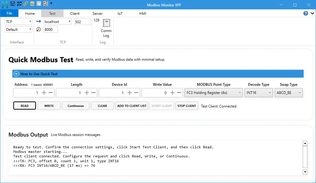
Before You Begin
You need the communication settings and register information from the device manual.
For a Modbus TCP device, identify:
- IP address or host name
- TCP port, normally
502 - Device ID (also called Unit ID, Slave ID, or Station ID)
- Register type and address
For a Modbus RTU or ASCII device, identify:
- COM port
- Baud rate
- Data bits
- Parity
- Stop bits
- Device ID
- Register type and address
Use Writes Carefully
Writing the wrong value can start equipment, change a setpoint, or alter device configuration. Confirm the address and permitted range in the manufacturer's documentation. During initial testing, use Read first. Enable writing only when the device and process are in a safe state.
Open Quick Modbus Test
- Start Modbus Monitor XPF.
- Configure the target connection in the Client ribbon:
- For Ethernet, select the correct protocol and enter the device IP address and port.
- For serial communication, select the COM port and match the device's serial settings.
- Open the Modbus Test tab or workspace.
- Expand How to Use Quick Test if you want to see the built-in reminder.
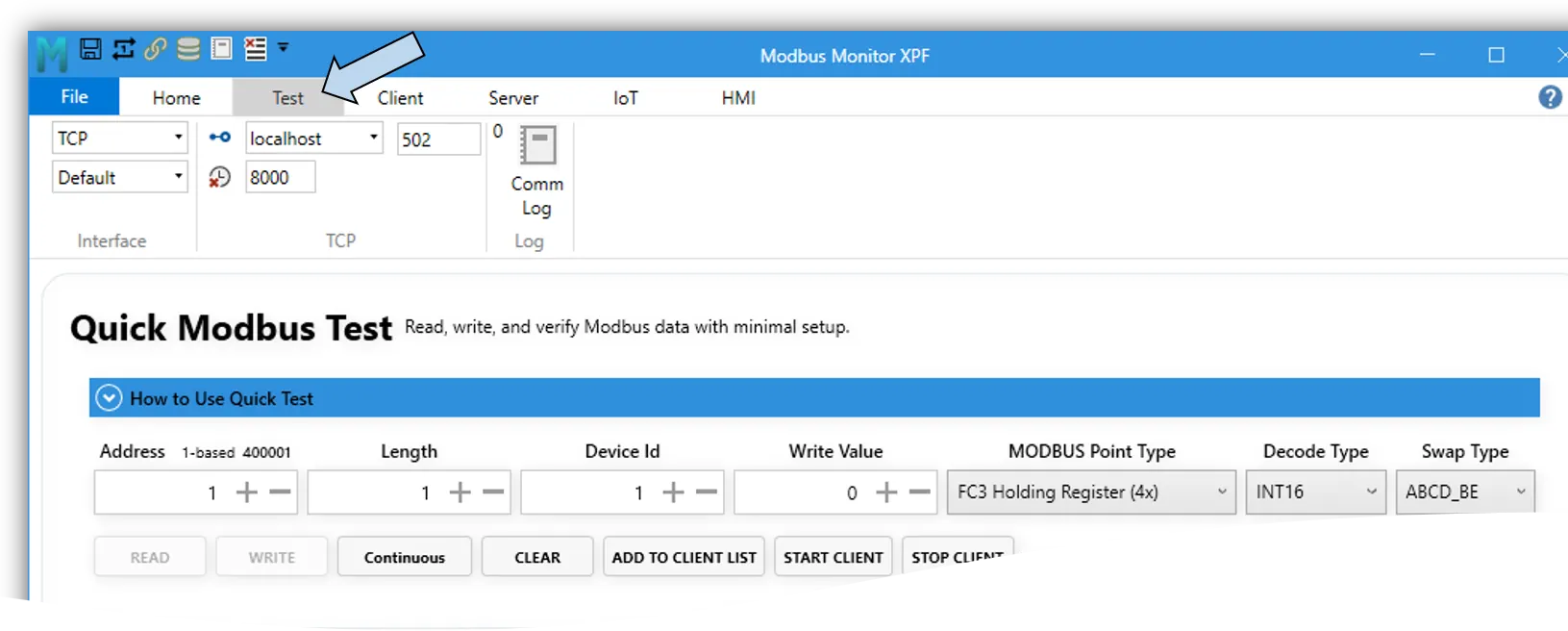
Understand the Request Fields
| Field | What It Means | Beginner Example |
|---|---|---|
| Address | Starting coil or register to test | 0, 1, or 400001, depending on addressing mode |
| Length | Number of coils or registers requested | Start with 1 |
| Device Id | Address of the Modbus server device | Often 1 |
| Write Value | Value sent when you click Write | Leave unchanged while testing reads |
| MODBUS Point Type | Selects the Modbus data area and function | Holding Register (FC03) |
| Decode Type | Converts raw register words into a useful value | UINT16, INT16, or FLOAT32 |
| Swap Type | Controls byte and word order | Start with ABCD_BE |
Point Types
| Point Type | Function | Typical Use | Read/Write |
|---|---|---|---|
| Coils | FC01 | On/off commands and outputs | Read and write |
| Discrete Inputs | FC02 | On/off status inputs | Read only |
| Holding Registers | FC03 | Setpoints, counters, and general values | Read and write |
| Input Registers | FC04 | Measurements and read-only values | Read only |
Function Code vs. Data Type
The Point Type selects where the data is stored and which Modbus function is used. The Decode Type controls how returned register words are interpreted. For example, a Holding Register can contain a UINT16, INT16, FLOAT32, or another supported value type.
Addressing Without Guesswork
Modbus manuals commonly describe the same physical location in different ways. Quick Modbus Test supports raw offsets and familiar reference-address notation.
If a manual gives you an address such as 40001, 400001, or a hexadecimal protocol offset, check it with the free Modbus register address calculator before testing. It shows the register type, 5-digit and 6-digit references, zero-based offset, and on-wire hexadecimal value together.
| Data Area | Function | Common Reference Example | First Zero-Based Offset |
|---|---|---|---|
| Coils | FC01 | 000001 |
0 |
| Discrete Inputs | FC02 | 100001 |
0 |
| Input Registers | FC04 | 300001 |
0 |
| Holding Registers | FC03 | 400001 |
0 |
Use the addressing control beside Address to switch between zero-based and one-based entry.
For example, a manual may call the first holding register:
400001in six-digit reference notation1in one-based offset notation0in zero-based protocol notation
These can identify the same physical register. Always check whether the manufacturer's register map starts at 0 or 1.
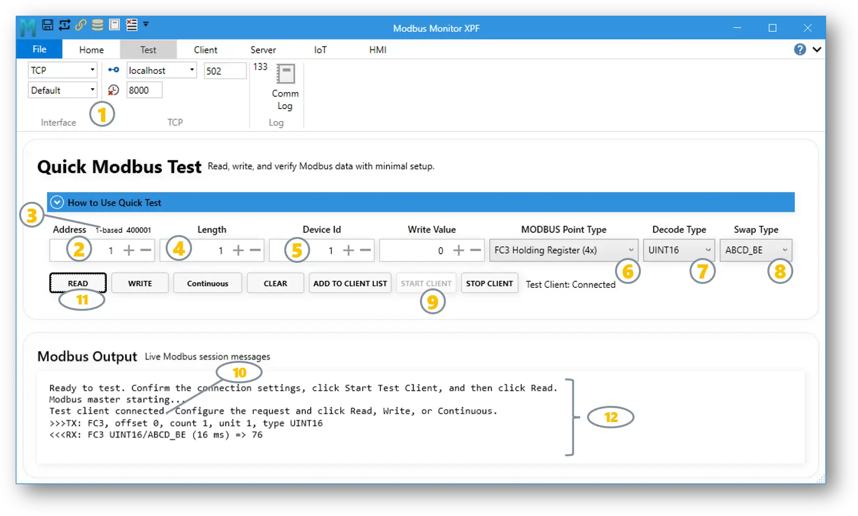
A Simple Address Test
If the device responds with Illegal Data Address, verify the Point Type first. Then check whether the manual's address needs a one-position offset. Avoid changing several settings at once; one controlled change makes troubleshooting easier.
Still unsure? Read zero-based vs. one-based Modbus addressing, then use the Modbus Address Calculator to confirm the conversion.
Read Your First Register
Use a known, read-only value for the first test, such as device temperature, voltage, status, or firmware version.
- Configure the connection in the InterFace section.
- In Quick Modbus Test, enter the Address.
- Set
1-basedor0-basedto toggle address mode. Click the label to change the mode. - Set Length to
1. - Enter the correct Device Id.
- Select the matching MODBUS Point Type.
- Start with UINT16 for a single unsigned register unless the device manual specifies another type.
- Start with ABCD_BE for Swap Type.
- Click Start Client.
- Confirm the status reads Test Client: Connected.
- Click Read.
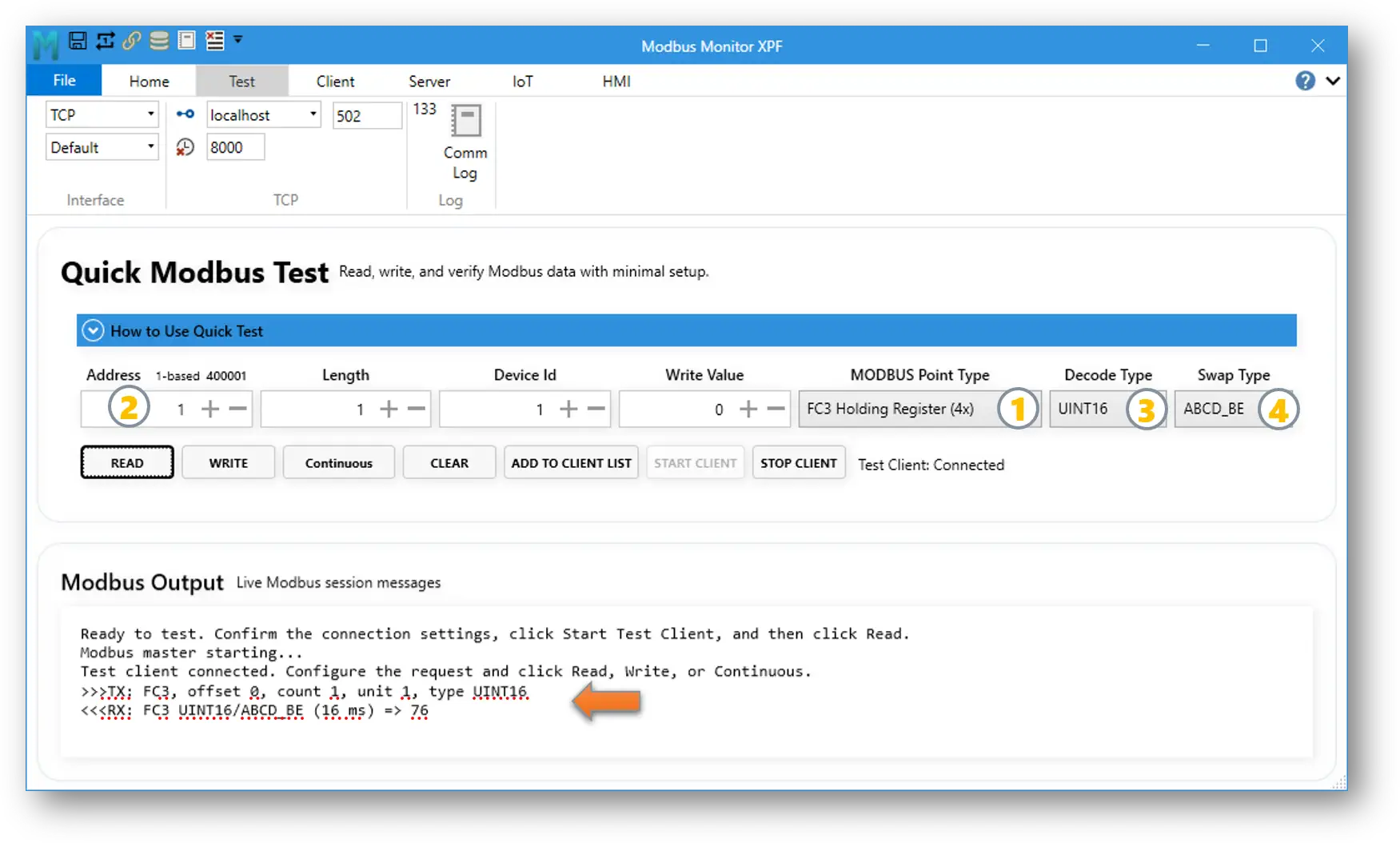
- Review the result in Modbus Output.
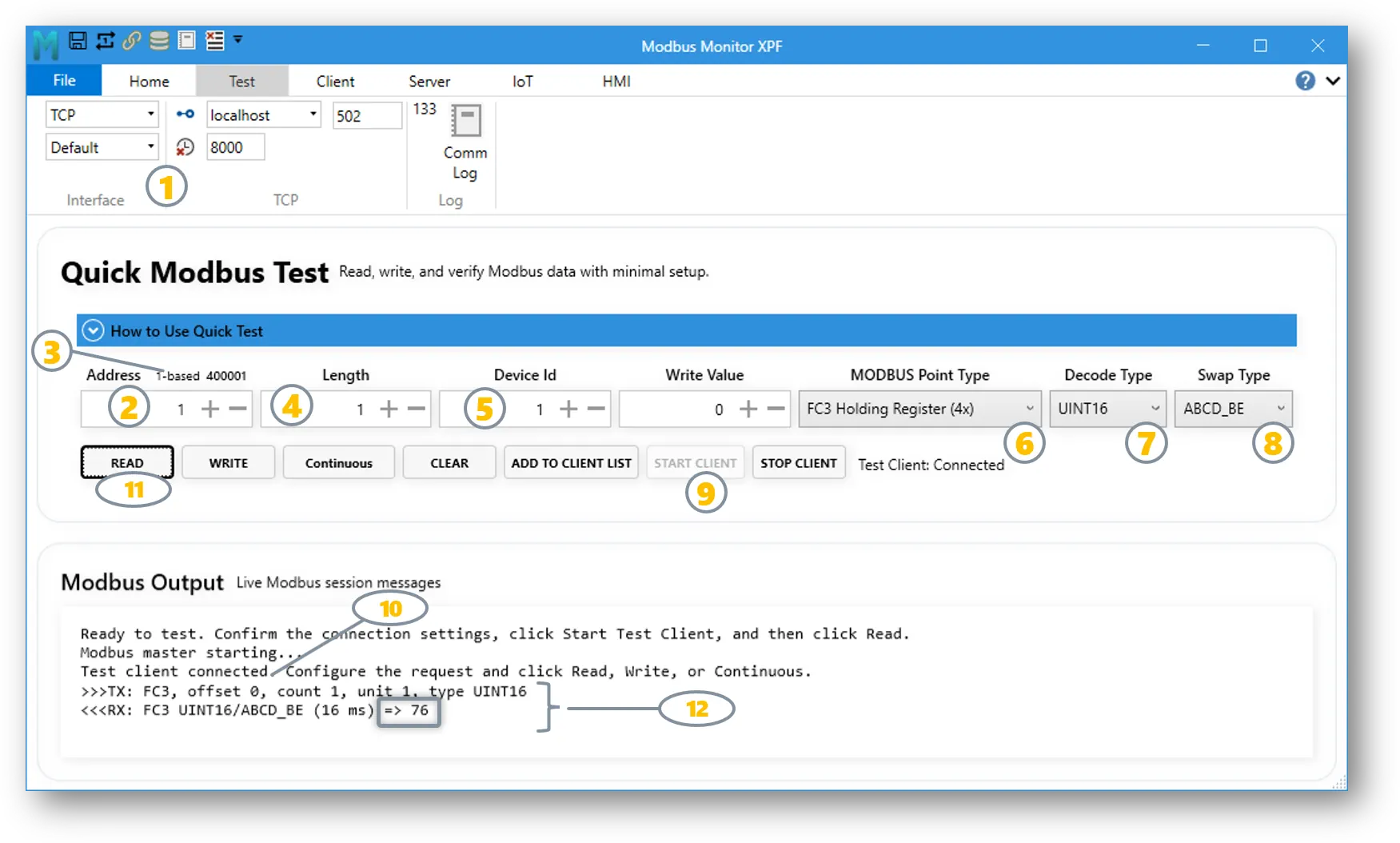
Reading Multi-Register Values
Some values use more than one 16-bit register:
| Decode Type | Registers Normally Required |
|---|---|
INT16 or UINT16 |
1 |
INT32, UINT32, or FLOAT32 |
2 |
INT64, UINT64, or DOUBLE64 |
4 |
When a selected decode type needs more registers, Quick Modbus Test automatically increases the effective read length and reports the adjustment in Modbus Output.
Interpret Modbus Output
The output area records the request and response so you can see what happened.
>>>TXdescribes the transmitted request.<<<RXdescribes the received response and decoded result.- Elapsed time shows how long the request took.
- An exception or error message explains why the request failed.
Use Clear to empty the output before a new troubleshooting test.
Correct a Value That Looks Wrong
A successful response does not always mean the displayed number is interpreted correctly. If the value looks unrealistic:
- Confirm the Point Type and Address.
- Check the device manual for the specified data format.
- Select the matching Decode Type.
- For 32-bit or 64-bit values, try the documented Swap Type.
- Read again after each change.
Common symptoms:
| Symptom | Likely Cause |
|---|---|
| Large positive value instead of a negative value | UINT16 selected instead of INT16 |
| Tiny, huge, or unstable decimal | Wrong FLOAT32 word or byte order |
| Correct response but wrong register | Zero-based vs. one-based address mismatch |
| No response | Connection settings, cable, IP address, port, COM settings, or Device ID |
Poll Continuously
After one successful read, use Continuous to watch the point update repeatedly.
- Keep the Test Client connected.
- Turn on Continuous.
- Watch new responses appear in Modbus Output.
- Turn off Continuous when the test is complete.
Continuous polling uses the configured scan rate, with a minimum interval of 100 milliseconds.
When to Use Continuous
Use continuous polling to observe a changing sensor, confirm stable communications, or compare a device display with the decoded Modbus value. For long-term monitoring, add the point to the Client list instead.
Write a Coil or Register
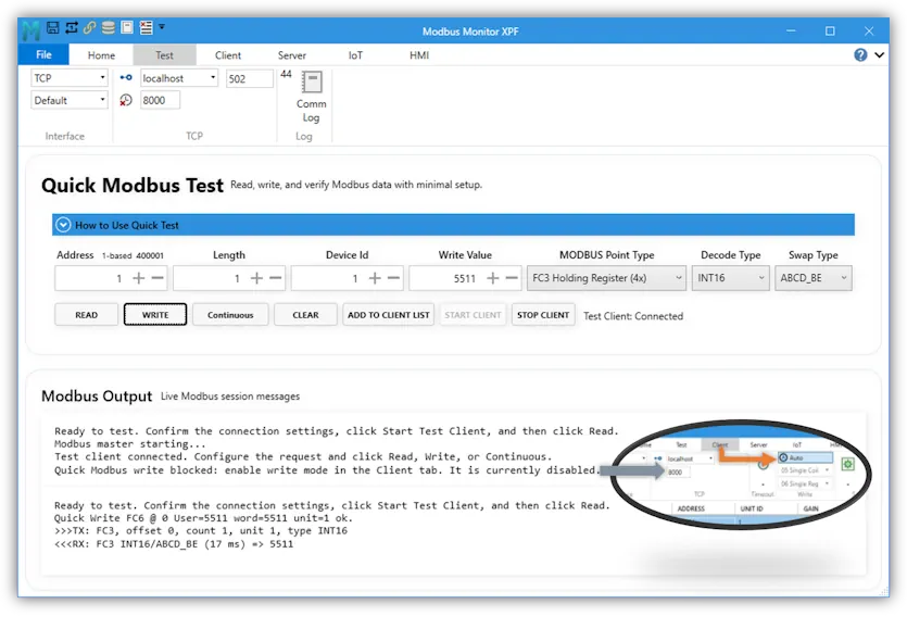
Quick Modbus Test can write coils and holding registers. Writing must first be enabled in the Client tab; if write mode is disabled, Quick Test blocks the operation.
- Confirm the device documentation permits writing to the address.
- Enable the appropriate write mode in the Client tab.
- Select Coils or Holding Registers as the Point Type.
- Enter the Address, Device Id, and Write Value.
- For registers, select the correct Decode Type and Swap Type.
- Click Write.
- Review the confirmation in Modbus Output.
- Click Read to verify the device accepted the new value.
For a coil, 0 means off and any nonzero write value means on. Depending on Client write settings, XPF uses the appropriate single or multiple write function.
Add a Verified Point to the Client List
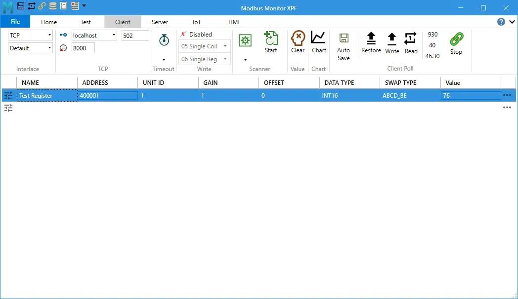
After the result is correct, click Add to Client List. XPF creates a new Client monitor point using the current:
- Address and addressing mode
- Device ID
- Point Type
- Decode Type
- Swap Type
The new point appears as Test Register in the Client monitor list. Rename it to a meaningful device tag, then use the normal Client workflow for continuous monitoring, charting, logging, limits, or HMI widgets.
For the complete monitoring workflow, see Modbus Client Operations and Monitor Points Configuration.
Troubleshooting
| Message or Symptom | What to Check |
|---|---|
| Modbus master is not running | Click Start Client and confirm the connection status |
| Connection timeout | Verify IP address, port, network path, firewall, or serial settings |
| Illegal Function | The device may not support the selected Point Type or function |
| Illegal Data Address | Check the register type, address, and zero-based/one-based mode |
| Illegal Data Value | Check Length, write value, and the device's allowed range |
| Wrong decoded value | Verify Decode Type, Length, and Swap Type |
| Write blocked | Enable write mode in the Client tab |
| Continuous stops | Check whether the Test Client disconnected or a communication error occurred |
Beginner Troubleshooting Order
Change one item at a time:
- Confirm the device is powered and reachable.
- Confirm IP/port or COM settings.
- Confirm Device ID.
- Confirm Point Type.
- Confirm Address and addressing mode.
- Confirm Decode Type.
- Confirm Swap Type.
This order separates communication problems from data-format problems and prevents random setting changes.
Quick Test Checklist
- The connection settings match the device.
- The Test Client shows Connected.
- Device ID matches the device.
- Point Type matches the register map.
- Addressing mode matches the register map.
- Read succeeds before writing is attempted.
- Decode Type and Swap Type produce a realistic value.
- The verified point has been added to the Client list if ongoing monitoring is needed.
Continue from Testing to Monitoring
Quick Modbus Test confirms one point. Modbus Monitor XPF can then monitor multiple devices, scan for registers, log values, plot trends, and build HMI dashboards from the verified addresses.
Download Modbus Monitor XPF View XPF Downloads and License Options