Arduino Modbus RTU Server
Transform your Arduino Uno into a fully functional Modbus RTU Server for seamless reading of Digital and Analog I/O using any Modbus Client.
Introduction
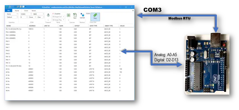
In this guide, we'll walk you through setting up your Arduino Uno as a Modbus RTU Server. This setup allows seamless reading of both Digital and Analog I/O using any Modbus Client. We'll provide comprehensive, step-by-step instructions, including sample code and a detailed project demonstration. By the end of this tutorial, you'll be able to effortlessly read Arduino's Analog and Digital inputs using the Modbus Monitor XPF Program.
Source Code
You can download the complete source code for the Arduino Modbus RTU Server Program from GitHub:
- GitHub Repository: Modbus-Monitor
- Arduino Server Project: ArduinoModbusServer
Arduino Sketch Setup
1. Create New Sketch
Start a new Arduino Sketch Program or use the example Blink program.
2. Include Required Library
Program your Arduino UNO as a Modbus RTU Server using the ArduinoModbus Open Source Modbus Library:
3. Configure Pins in Setup Function
Set up your Arduino pins in the setup() function:
pinMode(ledPin, OUTPUT);      // Pin 13 = LED with 1k Register
pinMode(12, INPUT_PULLUP);    // Pin 12 = DI - Connect GND to Turn OFF
pinMode(11, INPUT_PULLUP);    // Pin 11 = DI - Connect GND to Turn OFF
pinMode(10, INPUT_PULLUP);    // Pin 10 = DI - Connect GND to Turn OFF
pinMode(9, INPUT_PULLUP);     // Pin 09 = DI - Connect GND to Turn OFF
pinMode(8, INPUT_PULLUP);     // Pin 08 = DI - Connect GND to Turn OFF
pinMode(7, INPUT);            // Pin 07 = DI - Connect +5V to Turn ON
pinMode(6, INPUT);            // Pin 06 = DI - Connect +5V to Turn ON
pinMode(5, INPUT);            // Pin 05 = DI - Connect +5V to Turn ON
pinMode(4, INPUT);            // Pin 04 = DI - Connect +5V to Turn ON
pinMode(3, INPUT);            // Pin 03 = DI - Connect +5V to Turn ON
pinMode(2, INPUT);            // Pin 02 = DI - Connect +5V to Turn ON
4. Configure Serial Port and Modbus Server
In the setup() section:
Serial.begin(BaudRate);
ModbusRTUServer.begin(StationID, BaudRate);
ModbusRTUServer.configureCoils(0x00, 14);
ModbusRTUServer.configureDiscreteInputs(0x00, 14);
ModbusRTUServer.configureInputRegisters(0x00, 10);
ModbusRTUServer.configureHoldingRegisters(0x00, 14);
Mapping I/O to Modbus Registers
Digital I/O Examples
Read Digital Pin:
Write to Modbus Server Coil:
Analog I/O Examples
Read Analog Pin:
Write to Holding Register:
// Write to Modbus Address 0 of Holding Register
ModbusRTUServer.holdingRegisterWrite(0, holdingRegisterValue);
Main Loop Implementation
void loop() {
  // Declare variables
  int packetReceived;
  int pinval;
  int coilValue;

  // Just Blink Last State or Set to RUNNING
  StatusBlink(SERVER_STATUS_TYPE::RUNNING);

  // Poll for Modbus RTU requests
  ModbusRTUServer.poll();

  // Map the coil values to the discrete input values
  for (int i = 0; i < numCoils; i++) {
    // Modbus Map
    // 00001 = LED_BUILTIN   DO (Digital OUT)
    // 00002 = NOT USED      xxx
    // 00003 = LED_BUILTIN   DI (Digital IN)
    // 00004 = LED_BUILTIN   DI (Digital IN)

    // Map IO to Modbus Coils & Discrete Inputs
    // Starting with Modbus Address: 0 [000001]
    switch(i) {
      case 0:  // Modbus Address=0, ModbusMonitor Address (1-based)= 000001
        // RX
        break;

      case 1:  // Modbus Address=1, ModbusMonitor Address (1-based)= 000002
        // TX
        break;

      case 2:  // Modbus Address=2, ModbusMonitor Address (1-based)= 000003
      case 3:  // Modbus Address=3, ModbusMonitor Address (1-based)= 000004
      case 4:
      case 5:
        // Add more as needed
        coilValue = digitalRead(i);
        if(ModbusRTUServer.coilWrite(i, coilValue)) {
          // Success
        } else {
          // Failed
        }
        break;

      default:
        break;
    }

    // Read value
    coilValue = ModbusRTUServer.coilRead(i);           // 0x R/W

    // Write value to Discrete Inputs
    ModbusRTUServer.discreteInputWrite(i, coilValue);  // 1x RO
  }

  // Map the holding register values to the input register values
  for (int i = 0; i < numHoldingRegisters; i++) {
    // Map IO to Modbus Coils & Discrete Inputs
    // Starting with Modbus Address: 0 [000001]
    switch(i) {
      case 0:  // A0 = Modbus Address=0, ModbusMonitor Address (1-based)= 300001
      case 1:  // A1 = Modbus Address=1, ModbusMonitor Address (1-based)= 300002
      case 2:
      case 3:
      case 4:
      case 5:  // A5 = Modbus Address=5, ModbusMonitor Address (1-based)= 300006
        // 0 - 1023 for 0 to +5V
        holdingRegisterValue = analogRead(i);  // AI A0-A5, 0 to 1023
        break;

      default:
        holdingRegisterValue = (long)ServerStatus;
        break;
    }

    if(ModbusRTUServer.holdingRegisterWrite(i, holdingRegisterValue)) {
      // Success
    } else {
      // Failed
    }

    holdingRegisterValue = ModbusRTUServer.holdingRegisterRead(i);  // 4x R/W
    ModbusRTUServer.inputRegisterWrite(i, holdingRegisterValue);    // 3x RO
  }
}
Complete Source Code
See the full source code with all features at GitHub
Connect to Modbus Client
Upload the Program
- Connect the Arduino UNO to your computer
- Compile the program and fix any errors
- Upload your program to the Arduino
- Note the COM port used by Arduino from Windows Device Manager
Read Modbus Using Modbus Monitor XPF
You have two options to configure your Modbus client:
Option 1: Pre-configured Modbus Map (Recommended)
The pre-configured Modbus Map for this project can be downloaded from the Modbus Monitor XPF program's Online window.
Learn how to use the Online option
Option 2: Manual Entry
Add a register for each Modbus Address in the Arduino Program:
Example Mappings:
| Pin | Modbus Address | Address Value | Data Type | Description |
|---|---|---|---|---|
| Pin 2 | 3 (1-based) | 000003 | BIT | Digital Input Coil |
| A0 | 400001 | 400001 | WORD | Analog Input (Holding Register) |
Modbus Address Format: - Coils (Digital Output): 000001 - 099999 - Discrete Inputs (Digital Input): 100001 - 199999 - Input Registers (Analog Input): 300001 - 399999 - Holding Registers (Analog Output): 400001 - 499999
Configuration Steps
- Select COM Port in the Client tab of Modbus Monitor XPF
- Match Configuration parameters with Arduino settings
- Default: 9600 baud, 8N1
- Click Start to begin monitoring
- Observe Values updating as Arduino's Analog and Digital values change
- Example: Built-in LED (PIN 13) toggles between 1 and 0 at Modbus Address 13 (100013)
Modbus Register Mapping Reference
Digital I/O Mapping
| Arduino Pin | Modbus Coil Address | Modbus DI Address | Type | Notes |
|---|---|---|---|---|
| Pin 2 | 000003 | 100003 | Digital Input | Connect +5V to Turn ON |
| Pin 3 | 000004 | 100004 | Digital Input | Connect +5V to Turn ON |
| Pin 8 | 000009 | 100009 | Digital Input | INPUT_PULLUP, Connect GND to Turn OFF |
| Pin 13 | 000013 | 100013 | Digital Output | Built-in LED |
Analog I/O Mapping
| Arduino Pin | Holding Register | Input Register | Range | Notes |
|---|---|---|---|---|
| A0 | 400001 | 300001 | 0-1023 | 0 to +5V |
| A1 | 400002 | 300002 | 0-1023 | 0 to +5V |
| A2 | 400003 | 300003 | 0-1023 | 0 to +5V |
| A3 | 400004 | 300004 | 0-1023 | 0 to +5V |
| A4 | 400005 | 300005 | 0-1023 | 0 to +5V |
| A5 | 400006 | 300006 | 0-1023 | 0 to +5V |
Compatible Modbus Clients
- Modbus Monitor XPF (Windows) - Download
- Modbus Monitor Advanced (Android) - Download
- Any standard Modbus RTU client
Troubleshooting
Common Issues
Arduino not responding: - Check COM port in Device Manager - Verify baud rate matches (9600) - Ensure USB cable is data-capable
No data updating: - Verify Station ID matches - Check serial configuration (8N1) - Ensure Modbus polling is active
Incorrect values: - Verify Modbus address mapping - Check pin configuration in Arduino code - Confirm data type selection in client
Questions & Support
Need help with your Arduino Modbus Server setup?
- Community Forum: Visit Forum
- Contact Us: Get in Touch
- Report Issues: GitHub Issues
Post your questions in the Arduino Server section of our forum!